Site Plan Rendering Guide from 2D Plan to Client Visual
Learn what site plan rendering is, when to use 2D vs 3D, workflows, tools like ISO Mapper, and how to deliver fast client-ready site plan rendering visuals.
A client studies the black-and-white site plan, then looks up and asks, “Where do people enter, and how does this space connect to the building?” The drawing may be technically correct, but lines alone often don't communicate scale, access, grade, or atmosphere to a non-specialist.
That's where site plan rendering helps. It turns technical geometry into a visual explanation for design reviews, approvals, sales presentations, and stakeholder discussions. The right result isn't always photorealistic. Sometimes a disciplined 2D illustration communicates the proposal faster than a detailed 3D scene.
This guide focuses on the decisions that affect reliability and value: what a rendered site plan includes, when 2D beats 3D, which files must be verified, how the three main production paths compare, and how a fast hybrid workflow can produce client-ready visuals with ISO Mapper.
Table of Contents
- Introduction Why Site Plans Need More Than Lines
- What Site Plan Rendering Really Means
- When a 2D Illustrated Plan Beats a Full 3D Render
- What Makes a Site Plan Render Ready
- Three Ways to Produce a Site Plan Rendering
- Fast Client Ready Workflow With ISO Mapper and Best Practices
- Frequently Asked Questions About Site Plan Rendering
Introduction Why Site Plans Need More Than Lines
A site plan answers spatial questions, but it often answers them in the language of documentation. Property boundaries appear as lines. Building footprints become blocks. Roads, paths, planting areas, and parking are represented through symbols, hatches, or labels. An architect can interpret that information quickly, while a client may struggle to build a mental picture from it.
A rendered site plan adds visual hierarchy to the same underlying proposal. A darker surface can distinguish asphalt from paving. A restrained shadow can clarify building massing. Planting can identify a shared green or define a pedestrian route. Surrounding buildings and street context can show how the project sits within its setting.
Practical rule: Use rendering to clarify the plan, not to hide uncertainty in the plan.
The intended audience determines how much visual treatment makes sense. A planning discussion needs a graphic that stays close to the technical source. A sales presentation may benefit from warmer materials, active open spaces, and stronger atmosphere. An internal design review often needs a neutral image that makes circulation and spatial relationships immediately legible.
The same project can therefore require more than one visual. A top-down illustrated plan may support coordination, while an oblique aerial view may explain building height and terrain. An eye-level exterior render serves another purpose entirely, showing what it feels like to occupy an entrance, courtyard, or street.
For broader site decisions, a structured site analysis architecture guide can help teams separate existing conditions, opportunities, constraints, and proposed interventions before visual production begins. That separation matters because a polished image can still be misleading if the source geometry is incomplete.
The practical sequence is straightforward:
- Identify the decision the image must support.
- Choose 2D, 3D, or a hybrid deliverable.
- Verify the source package.
- Produce the visual with controlled hierarchy.
- Compare the output against the source before delivery.
What Site Plan Rendering Really Means
Think of the technical site plan as a map. It records where things are and how they relate. A rendered site plan is the illustrated guide layered over that map, adding enough color, texture, shadow, and context to help someone understand the proposal without decoding every line convention.
That added information should have a job. A lawn texture identifies open space. A paving treatment separates pedestrian movement from vehicles. A soft shadow helps a viewer read building placement. Trees can define an edge or indicate the intended character of a courtyard. Decorative detail that doesn't improve understanding is usually noise.
Three deliverables people often confuse
A 2D illustrated plan stays overhead and close to the source drawing. The team may add color, texture, shadows, trees, labels, and diagrammatic graphics in Photoshop, Illustrator, or similar software. This format suits planning diagrams, early design reviews, and presentation boards where exact plan organization matters more than spatial drama.
A 3D massing or shaded bird's-eye view introduces height, depth, terrain, and perspective. It can show how buildings relate to one another, how slopes affect the site, or how an approach road frames the development. This output requires more geometry or a dependable 3D source because the camera and vertical relationships affect what the viewer sees.
An exploratory style variation keeps the plan or model as a visual reference while testing different materials, planting treatments, lighting, or presentation languages. A restrained architectural graphic, a softer illustrative treatment, and a more atmospheric marketing view may all communicate the same design at different stages.
Match the output to the question
An isometric site map is useful when the viewer needs a compact sense of arrangement and depth. A site analysis graphic is more useful when the purpose is to explain movement, solar exposure, vegetation, access, or other relationships through overlays and labels. Neither output replaces editable BIM, CAD, or a coordinated model. A render is a presentation layer, not the authoritative geometry.
A useful mental model is:
- Technical drawing owns accuracy.
- The 3D model owns controlled perspective and massing.
- The rendered visual owns communication, hierarchy, and atmosphere.
That distinction prevents a common mistake, choosing a tool before deciding what the image must communicate. For a fuller explanation of how visualization differs from underlying design information, see this overview of architectural rendering meaning.
When a 2D Illustrated Plan Beats a Full 3D Render
More realism isn't automatically more useful. A highly detailed bird's-eye scene can bury the information a client needs: the road hierarchy, the boundary, the distance between buildings, or the location of a shared zone. If the decision concerns arrangement rather than atmosphere, a clean 2D plan may be the stronger deliverable.
For permit coordination and early concept reviews, the viewer often needs to answer a short list of questions quickly:
- Where are the buildings?
- How do vehicles enter and circulate?
- Which paths are public, private, or service routes?
- Where are the gathering areas?
- How does the proposal relate to the property edge?
Color, texture, and shadow can be added directly to a CAD export in Photoshop or Illustrator. This approach preserves the top-down relationship between elements and gives the designer precise control over labels, linework, and emphasis. It also avoids building a full 3D scene when the camera won't change.
A simple decision test
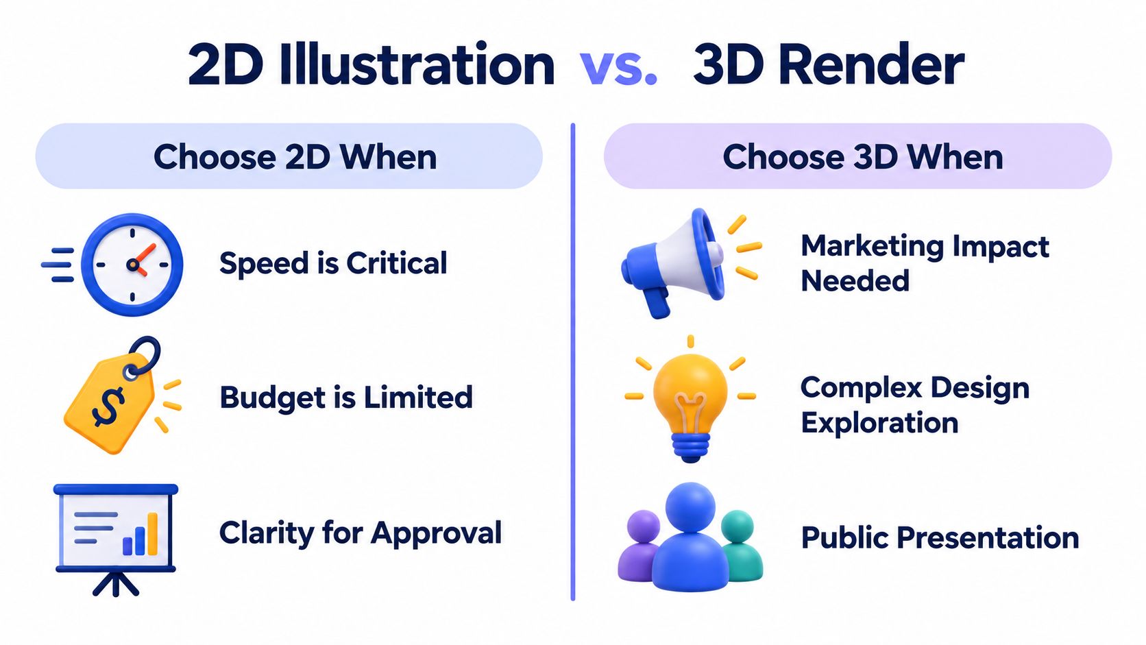
Choose 2D first when:
- Clarity drives the review: Approval and coordination audiences need unmistakable boundaries, circulation, and zones.
- The deadline is tight: A presentation graphic can be produced without modeling every terrain, tree, façade, and context element.
- The budget is limited: A controlled illustration avoids the labor associated with full scene setup and repeated 3D revisions.
- The design is still moving: A 2D plan can be updated directly from the latest drawing without rebuilding a detailed environment.
- Labels matter: A diagram can combine visual treatment with annotations more cleanly than a busy perspective.
Choose 3D when the design question depends on vertical relationships. Terrain changes, building height, stepped massing, retaining conditions, and surrounding context are difficult to communicate through a flat graphic alone. A 3D bird's-eye view also has a stronger role in marketing when the image must establish character, experience, and a sense of place.
Published guidance notes that a straightforward 3D site plan may take one to three days, while larger developments can take a week or more. See the site plan rendering guide for that workflow context. The point isn't that 3D takes too long. The point is that fidelity should match the decision and available effort.
Line-weight hierarchy can make a 2D plan substantially easier to read. Published drafting guidance places property lines around 0.18–0.25 mm, roads and infrastructure around 0.25–0.35 mm, building outlines around 0.35–0.50 mm, and cut lines or strong plan edges around 0.50–0.70 mm. These ranges come from architectural line-weight guidance, and larger scales generally need heavier weights while smaller scales need lighter ones.
The practical lesson is simple: make primary geometry visually dominant, then let secondary information recede. A 2D plan with disciplined hierarchy can communicate faster than a photorealistic image with inconsistent contrast.
For readers moving between interior documentation and exterior graphics, a floor plan rendering workflow provides useful context on how plan geometry becomes a presentation visual.
What Makes a Site Plan Render Ready
A render-ready plan starts with verified project information. Before any visual treatment, confirm the boundaries, levels, existing conditions, intended materials, and required output. A polished image cannot correct an incorrect property line or misplaced building footprint.
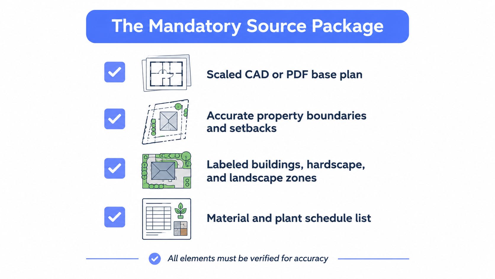
The base package should combine a boundary survey, topographic contours or spot elevations, existing-condition records, surrounding context, and photographs from relevant approach directions. These files establish the relationships that a flat drawing may not show clearly, including massing, grade changes, access, and nearby structures. The technical discussion of survey data for site plan rendering explains how source information affects visual accuracy.
Files that establish geometry
Use the following source groups as a pre-render checklist:
- Boundary information: A survey or verified drawing showing property lines, relevant easements, and the project extent.
- Topographic information: Contours, spot elevations, or another dependable record of grade.
- Architectural geometry: A clean CAD drawing or BIM export showing building footprints, roads, parking, paths, walls, and major hardscape.
- Existing conditions: Trees, utilities, drives, retained structures, walls, and other elements that affect what can be placed or removed.
- Context: Adjacent buildings, streets, street sections, nearby surroundings, and photographs from approach directions.
- Design intent: Planting zones, material schedules, planting direction, and known surface specifications.
- Visual brief: Required resolution, output format, preferred camera or view, audience, and presentation character.
A useful package is organized before visualization begins. Name files clearly, confirm the latest revision, and record which information is approved versus still under development.
Where possible, use georeferenced DWG or DXF files so the project aligns consistently with survey and context data. A CAD or BIM file without a shared spatial reference may still work, but orientation, scale, units, and origin must be checked before surrounding information is added. Use this CAD geometry checklist to identify geometry problems before they reach the final image.
What can be estimated and what cannot
Presentation details allow some interpretation. If the final species list is unfinished, the renderer can apply a restrained planting style. If the exact product has not been selected, surface appearance can remain simplified while following the known material intent. Soft daylight and limited entourage can also stay illustrative.
Do not estimate property boundaries, setbacks, grade changes, building placement, utility locations, retained structures, or circulation geometry. An attractive image based on incorrect information creates coordination work instead of resolving a communication need.
Quality-control checkpoint: Overlay the source drawing and proposed render before generation. Verify boundaries, building footprints, access routes, hardscape edges, and major planting zones.
Check slopes and paving placement closely. Missing survey or topographic information raises the risk of incorrect grades, misplaced surfaces, and inconsistent relationships between the site and its surroundings. Faster image generation increases the value of this review because errors can otherwise pass through the workflow unnoticed.
Common source materials also include architectural CAD drawings or BIM models, site and topographic surveys, finish schedules, and reference images. The exact package varies, but the rule remains consistent: the render should preserve verified relationships and clearly mark any detail that is still interpretive.
Three Ways to Produce a Site Plan Rendering
The production method should follow the decision the image needs to support. A 2D illustrated plan usually beats a 3D render when reviewers must compare boundaries, access, zones, and labels quickly from above. A 3D workflow becomes more useful when terrain, height, vertical relationships, or several fixed viewpoints determine the decision.
Direct 2D illustration
A designer exports a clean plan from CAD and builds the presentation layer in Photoshop, Illustrator, Affinity Photo, or similar software. This gives precise control over surfaces, labels, trees, shadows, colors, and graphic overlays. It suits top-down planning diagrams, early concepts, approval graphics, site plans, and presentation boards where legibility matters more than photographic realism.
The main cost is design labor. One carefully controlled view can be efficient, while repeated alternatives require manual edits to materials, symbols, annotations, and shadows. The source still needs verified geometry. Illustration can clarify a plan, but it cannot correct an uncertain boundary or misplaced building footprint.
Traditional 3D production
A team builds or refines a site model in BIM, CAD, or a 3D application, then sets cameras and produces shaded, rendered, or photorealistic views. This is the dependable route for terrain, massing, grade changes, vertical relationships, and multiple controlled cameras.
The model remains editable during design development. Setup requires more time, software knowledge, hardware or cloud-rendering capacity, and coordination. A documentation model may also need terrain cleanup, simplified surrounding context, planting, materials, and camera composition before it is ready for presentation.
AI-assisted generation
A clean plan image can guide the addition of materials, planting, atmosphere, and depth. The source plan controls the organization, while the generated image supplies a fast visual treatment. This works well for style exploration and early client comparisons, but it is not a verified replacement for a 3D model when the team needs a new viewpoint or exact geometry.
Vizcraft's isometric map generator is one example of a plan-driven tool. Used in a hybrid process, it can develop a presentation layer while CAD or BIM remains the authority for dimensions and relationships.
| Workflow | Typical Turnaround | Cost Signal | Best For |
|---|---|---|---|
| Direct 2D illustration | Depends on plan complexity and manual detailing | Design labor and revision time | Approval graphics, site plans, concept boards |
| Traditional 3D model and render | Longer setup, especially when terrain and context need modeling | Modeling, software, hardware, and rendering labor | Controlled cameras, massing, terrain, multiple views |
| AI-assisted plan rendering | Fast generation after source preparation | Per-render or credit-based pricing, plus review time | Early variations, materials, atmosphere, client exploration |
For tool-specific cost planning, review Vizcraft pricing. Compare the path against the required control, number of views, revision frequency, and review effort. A lower generation cost does not remove the need to check geometry and labels.
A hybrid process often fits projects with tight deadlines: keep verified geometry in CAD or BIM, export a clean plan, generate visual options quickly, then manually correct labels, edges, and relationships that affect the decision.
Fast Client Ready Workflow With ISO Mapper and Best Practices
A client review can fail before styling begins. A boundary may be cropped, a path may be hidden by annotations, or an unverified grade may make an attractive image misleading. Start with the source file and decide which information must remain authoritative.
Remove construction notes, duplicate dimensions, and unrelated layers from the presentation export. Keep building footprints, relevant openings, circulation, zones, and major boundaries readable. The image should function like a clear map: visual emphasis can change, but the relationships cannot.
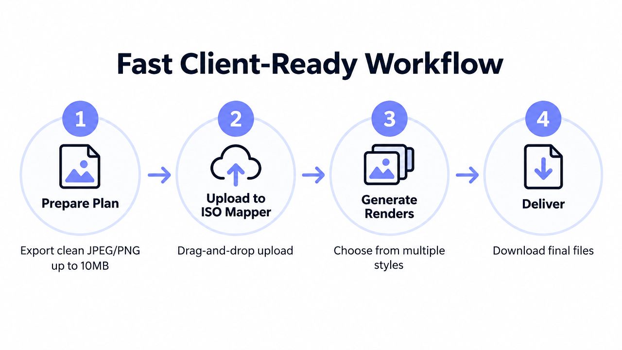
ISO Mapper accepts a JPEG or PNG floor plan up to 10 MB and analyzes room layouts, walls, openings, and spatial relationships to create a 3D isometric cutaway with turnaround depending on the input and workflow, according to its published workflow at ISO Mapper. For a site-oriented image, the plan must still show the site organization clearly. The tool can develop the visual layer, but it cannot validate a boundary survey or correct an unverified grade.
Prepare and upload
Export a clean image at a useful resolution. Check orientation, confirm the crop includes the complete review area, and remove visual noise before uploading. Select a restrained visual direction first, then add atmosphere after the structure has passed review. Cloud processing means the workflow does not depend on a local GPU or render farm.
Judge the first output by structure, not decoration:
- Geometry: Do building footprints and major edges remain in their correct positions?
- Openings and access: Are entries, paths, drives, and circulation still readable?
- Proportion: Does the image preserve the relationships in the source?
- Scale: Do planting, vehicles, furniture, or other entourage suggest plausible scale without covering key information?
- Hierarchy: Do buildings and circulation read before texture and decoration?
Generate variations only after the base reading works. During a live client review, a neutral diagrammatic treatment and a warmer presentation option can clarify how styling changes interpretation. Keep every option traceable to the same verified source.

Control the presentation layer
Use line weights deliberately when the source includes linework. Give primary geometry the strongest contrast, keep property information visible but subordinate, and avoid heavy shadows that blur edges. Use color to distinguish categories, not to make every surface compete for attention.
Keep entourage consistent across variations. Changes in tree scale, vehicle placement, or people density can make options difficult to compare. For boards and proposals, export at high resolution and inspect the final file at the size clients will see. Small labels and boundary lines may disappear during layout even when the working image looked clear.
Keep a render history during review so the team can compare options without losing earlier versions. Archive the verified source drawing separately. The generated image is a visual deliverable, not the project record.
The published Vizcraft pricing structure lists Starter at $19 per month for 25 renders, Pro at $49 per month for 100 renders, and Studio at $99 per month for 250 renders, with one-time packs from $7 and a stated per-render range of $0.40–$0.76. Review the current pricing details before budgeting. Choose a plan according to expected iteration, not the first image alone.
You can evaluate the workflow with 2 free credits on signup and no credit card required. Begin with a clean plan, compare the generated visual against its source, and correct geometry, labels, and relationships before deciding whether it is ready for the client or project.
Frequently Asked Questions
Can a site plan be rendered without a 3D model?
Yes. Export a clear plan image for a 2D illustrated plan or a plan-driven visualization. This approach often works better than a full 3D render when the goal is to compare zoning, circulation, planting, or presentation options quickly. Build a 3D model when the review depends on new camera angles, terrain depth, or controlled vertical relationships.
What files are needed for a trustworthy result?
Begin with a clean CAD, BIM, or plan export. Verify the boundary survey, topography, existing conditions, surrounding context, material intent, and reference photographs before rendering. A plan image supports presentation development, but it cannot confirm that boundaries, grades, or utilities are correct. The source data is the project record, while the render is a visual explanation of it.
How fast can an isometric plan render?
Vizcraft's ISO Mapper workflow states that a JPEG or PNG floor plan up to 10 MB can produce a 3D isometric cutaway with turnaround depending on the input and workflow. That describes image generation only. Cleanup, source comparison, corrections, and final export still require human review.
What does site plan rendering typically cost?
Costs depend on manual labor, modeling requirements, revisions, and tool pricing. Vizcraft lists monthly plans and one-time packs, but the budget should also cover verification and refinement. Choose the workflow based on expected iteration, not the first image alone.
Vizcraft provides ISO Mapper for converting plan images into 3D isometric visuals and producing variations for client reviews. Try Vizcraft with 2 free credits and no card required, then compare each result against the verified source plan before using it in a proposal or design review.