Schematic Drawings Architecture: A Practical Guide
Schematic Drawings Architecture. Learn what schematic drawings in architecture actually show, which project phases they cover, and how to read and produce them
You're in a client meeting with a table full of program notes, site constraints, and half-formed ideas. After weeks of discussion, you spread out a plan with rooms reduced to clear shapes, a few circulation lines, and a loose massing view. The client traces the route from the entry to the kitchen, pauses at the shared workspace, and points to the room they've been trying to describe since the first meeting.
That moment is why schematic drawings in architecture matter. A schematic plan is often the first artifact that turns an abstract wish list into measurable spatial decisions. It shows what fits, what conflicts, and what still needs to be decided before the project becomes expensive to change.
At this stage, the set may include bubble diagrams, single-line plans, loose elevations, and simple massing views. It should be clear enough to test the program, but restrained enough that nobody mistakes it for a construction document. The distinction protects the project from premature detailing and helps clients focus on the decisions that govern scope.
Good presentation techniques can make that conversation more productive. The guidance on interior design client presentations is useful when you need to explain spatial choices without burying them under technical information.
Table of Contents
- The Moment a Project First Becomes Real to a Client
- What Schematic Drawings Actually Are in Architecture
- Typical Components in a Schematic Drawing Set
- How Schematic Drawings Differ From Design Development and Construction Documents
- How to Produce a Schematic Plan From Program to Sign-Off
- Turning Schematic Plans Into Client-Ready Visuals
- Common Misconceptions About Schematic Drawings
- Key Takeaways and Frequently Asked Questions
The Moment a Project First Becomes Real to a Client
From conversation to measurable space
Programming conversations are mostly verbal. A client describes a quieter bedroom, a more generous arrival, a kitchen that connects to family life, or an office that can close off during meetings. Those descriptions matter, but they don't yet reveal the conflicts between area, circulation, structure, daylight, access, and budget.
The schematic plan makes those conflicts visible. A corridor now occupies measurable space. A room has an actual relationship to its neighbors. The client can see whether the entry leads naturally to the living area or forces visitors through a private zone. The design team can test whether the stated program fits the site rather than assuming that every request can coexist.
Practical rule: Use schematic drawings to make decisions visible, not to make the project look finished.
A first package often starts with a bubble diagram that tests adjacency and movement. The bubbles then become a single-line plan, where walls are represented as simple strokes and room areas are labeled without pretending that partitions, finishes, and assemblies have been resolved. A loose massing view adds the third dimension, helping the client understand whether the plan produces a compact volume, a courtyard arrangement, or a more fragmented composition.
Where scope discipline starts
Clients naturally ask for more detail once they recognize the project. They may want exact windows, cabinetry, furniture layouts, material changes, or a fully coordinated reflected ceiling plan. Those requests aren't unreasonable, but most belong later, after the basic arrangement has been accepted.
The architect's job is to explain the consequence of adding detail too early. A fully specified wall type can imply a decision that the team hasn't tested. Detailed window locations can make a client believe the façade is fixed. A precise-looking rendering can turn an exploratory option into an emotional commitment before the plan has been validated.
Schematic drawings occupy a productive middle ground. They're structured, scaled, and deliberate, but they preserve room for alternatives. They allow the team to compare a shifted core, a different entrance sequence, or a revised massing strategy while revisions are still manageable.
The rest of this guide focuses on that working boundary. It covers the definition of schematic drawings, sheet conventions, typical components, differences between project phases, a repeatable production workflow, presentation options, common misconceptions, and practical questions from clients and junior staff.
What Schematic Drawings Actually Are in Architecture
Schematic drawings are the deliverable package produced during the schematic design phase. Their purpose is to test spatial concepts, confirm that the program fits, and secure early alignment before structural, mechanical, electrical, and plumbing decisions become heavily committed.
A useful schematic set answers basic questions:
- Does the program fit the site and proposed building area?
- Do the major rooms have sensible adjacencies?
- Can people move through the building without awkward conflicts?
- Does the massing support the client's priorities?
- Are zoning, access, life-safety, and budget issues visible enough for early review?
The drawings are typically less resolved than design development documents and substantially less complete than construction documents. That isn't a weakness. It keeps the design team fast and makes it cheaper to revise the decisions that still need testing.
Working conventions that support clarity
Metric offices commonly use plan scales such as 1:200 or 1:100, while imperial projects often use 1/8 inch or 1/4 inch per foot for schematic plans. A 24 by 36 inch sheet is a common presentation format, with smaller sheets acceptable when the scope and scale remain readable, as described in technical schematic drawing guidance.
The line hierarchy should communicate importance without implying construction precision. Primary walls are usually heavier, door swings remain light, room labels are prominent, and secondary information can be dashed or screened. Finish tags, detailed wall types, complete dimensions, and fully coordinated consultant information usually stay out of the set.
For teams reviewing printing requirements, the blueprint printing guide from Camelot Print & Copy Centers provides useful background on sheet preparation and reproduction.
The bridge between phases
Programming provides the requirements. Schematic design tests those requirements spatially. Design development resolves the selected direction, and construction documents explain how the approved design will be built.
A schematic package therefore has a specific tolerance for ambiguity. It may include a basic structural idea, a preliminary system narrative, or an early code note, but it shouldn't present unresolved assumptions as final technical decisions. The broader family of architectural drawing types helps place schematic work within the larger drawing set.
A public-sector design manual describes schematic design as a preliminary alternatives phase and identifies it as the 20% design milestone, followed by 50% design development and 90% construction documents. Its listed schematic deliverables include floor plans, sections, elevations, massing drawings, site plans, and related visual descriptions. That convention reinforces the central point: schematic drawings are formal project documents, but they're early decision documents rather than build instructions. Public-sector design phase guidance supports that distinction.
Typical Components in a Schematic Drawing Set
A schematic set should tell a coherent story from site to room. It doesn't need every answer, but it should make the major questions easy to locate and discuss.
Start with orientation and project control
The cover sheet identifies the project, drawing issue, scale conventions, and basic code or zoning assumptions. Keep the code summary concise. At this stage, it should identify the governing constraints and open questions rather than imitate a final code analysis.
The site plan establishes the building's position in relation to setbacks, access, neighboring conditions, sun orientation, topography, and major site features. It may be drawn at a smaller scale than the floor plans because its job is to explain fit and orientation, not construction layout.
A useful site plan often shows:
- Setbacks and property limits, so the client understands the buildable envelope.
- Primary access, including vehicles, pedestrians, service movement, and emergency approach.
- Orientation, including north and the basic relationship to sun and views.
- Major site constraints, such as existing buildings, significant trees, slopes, or easements.
Let the plans carry the program
Floor plans are the working center of the package. They should show room names, approximate areas, major partitions, door swings, stairs, cores, principal circulation, and enough furniture or equipment to test usability. Area callouts can use square feet or square meters, depending on the project and client.
Basic egress paths belong here when they affect planning. So do preliminary structural grid hints, core locations, and generic zones for service spaces. The plan should show whether the project works as an arrangement of spaces, not whether every wall has a finished specification.
For a clear reference on reading the graphic language, use this guide to floor plan symbols. It helps junior designers keep notation legible without filling an early plan with unnecessary technical tags.
Use sections and elevations to explain volume
A section is essential whenever floor-to-floor relationships, grade changes, double-height spaces, roof form, or vertical circulation influence the concept. One well-chosen section can explain more than several additional plan annotations.
Simple elevations communicate massing, openings, proportion, and the relationship between solid and void. They don't need final materials or complete façade detailing. A roof plan outline can clarify the building's footprint, drainage concept, roof geometry, and relationship to the site.
Add an isometric or axonometric view when the client struggles to read plans. An isometric drawing represents a three-dimensional object on a flat surface while preserving its shape and proportions. An isometric floor plan can show room connections and vertical relationships in a way that a flat plan can't.
A schematic set communicates spatial relationships and project viability, not constructibility.
What should stay out
Full dimensions, detailed wall types, window specifications, fixture counts, ceiling details, and MEP routing generally belong later. Adding them early often creates false certainty and invites line-by-line review of decisions the team meant to keep flexible.
The same principle applies to consultant coordination. A preliminary structural bay or mechanical zone may be useful. A fully coordinated structural and MEP layout usually signals that the project has moved into design development, even if the title block still says schematic design.
How Schematic Drawings Differ From Design Development and Construction Documents
The three phases differ less by appearance than by the decision each drawing set is expected to support. A schematic plan asks whether the concept works. Design development asks whether the building works as a coordinated system. Construction documents explain how contractors are expected to build it.
| Phase | Typical Plan Scale | Level of Detail | Primary Audience | Decision Locked |
|---|---|---|---|---|
| Schematic Design | 1:200 or 1/8 inch = 1 foot | Program, massing, adjacencies, basic code and system assumptions | Client, architect, early consultants | Does the concept work? |
| Design Development | 1:50 or 1/4 inch = 1 foot | Coordinated plans, assemblies, structure, systems, and materials | Client, architect, consultants, cost team | Does the building work? |
| Construction Documents | 1:20 or 1/2 inch = 1 foot notes and details | Buildable dimensions, specifications, schedules, details, and coordination | Contractor, subcontractors, permitting authorities | How exactly do we build it? |
Scale changes the conversation
At schematic scale, a wall is often a graphic boundary. In design development, that wall needs a realistic thickness, assembly logic, relationship to structure, and coordination with doors, windows, equipment, and services. In construction documents, the same wall may require enlarged details, dimensions, material references, fire ratings, and installation information.
That progression is why over-detailed schematic drawings create problems. The client may assume that a detailed-looking opening, finish, or partition has already been selected. The contractor may read a graphic convention as a technical commitment. The architect then spends time correcting expectations instead of advancing the design.
Under-detailing construction documents creates the opposite risk. Contractors need enough information to price and build the work, while permitting authorities need drawings that demonstrate compliance. A schematic set can't carry that burden because it lacks the coordinated dimensions, specifications, and systems information that construction requires. The practical distinction is well illustrated by Pinnacle Property Media's approach to construction documentation.
Phase test: If the drawing answers a question that belongs to the next phase, check whether the project is being advanced too quickly.
How to Produce a Schematic Plan From Program to Sign-Off
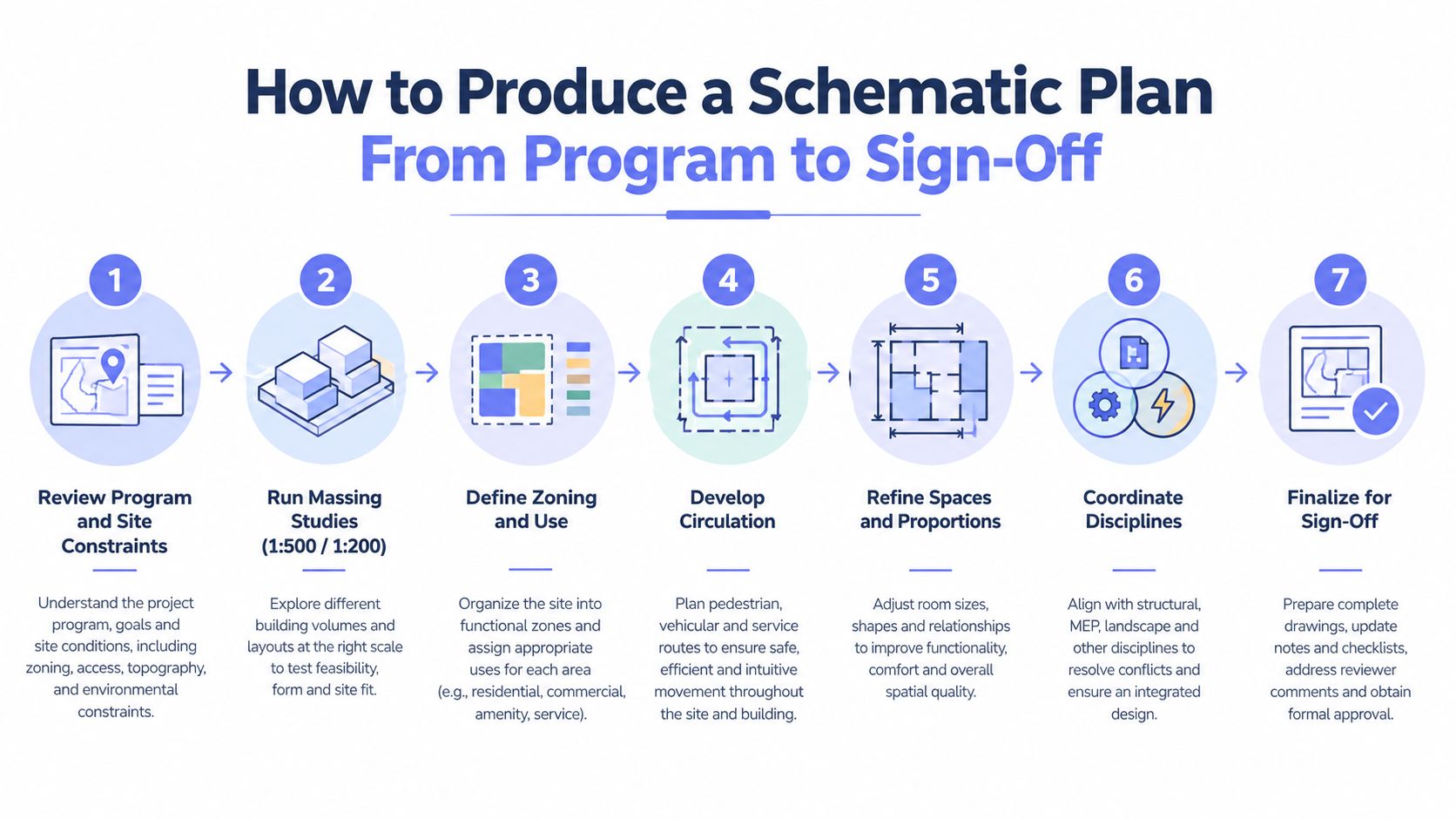
A junior designer can produce a reliable schematic plan by treating each step as a decision checkpoint rather than a drafting exercise.
Seven steps that keep the work moving
-
Review the program and site constraints. Confirm the required spaces, approximate areas, occupancy assumptions, access conditions, setbacks, orientation, and known jurisdictional restrictions. Mark uncertainties before drawing geometry.
-
Run massing studies at 1:500 or 1:200. Test building footprint, height, orientation, open space, and access with quick volumes. Keep several options alive long enough to compare their consequences.
-
Build the bubble diagram. Group public, private, service, circulation, and support functions. Draw the desired relationships before assigning exact walls.
-
Develop the single-line plan. Translate the strongest bubble arrangement into rooms and circulation at the agreed schematic scale. Add stairs, cores, major openings, and basic furniture only where it helps test function.
-
Add grids and structural logic. Place dimensioned grid lines, core locations, and basic structural bays once the plan has a credible arrangement. These are planning controls, not final engineering.
-
Layer in early code notes. Identify egress width, fire-rating assumptions, accessible routes, setbacks, and other constraints that could invalidate the concept. Keep the notes clear about what has been confirmed and what remains subject to review.
-
Package the review set. Issue the plans, one section, one or two elevations, the site plan, and a massing or isometric view when volume needs explanation. Include an assumptions list and clear decisions required from the client.
Set revision boundaries
The most important checkpoint comes after the client has reviewed the plan and the team has recorded decisions. Once a plan is dimensioned and signed off, moving structural bays, relocating the core, or changing the primary circulation strategy shouldn't be treated as a casual schematic edit. Those changes affect the agreed direction and may belong to design development or a formally documented revision.
A decision log prevents the same conversation from reopening. Record the selected option, unresolved items, responsible reviewer, and date of the next decision. The workflow advice in design project management is relevant here because schematic work depends as much on decision control as on drawing skill.
When a client is learning to interpret the set, guidance on reading schematic floor plans can provide a useful nontechnical reference. The architect should still lead the discussion, but a shared vocabulary reduces confusion during review.
Turning Schematic Plans Into Client-Ready Visuals
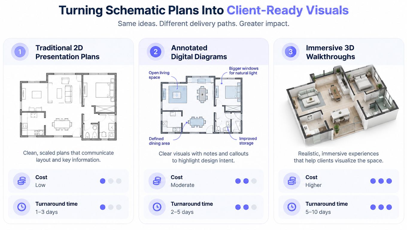
A clean schematic plan is valuable to an architect, but clients often need more than linework to understand volume, hierarchy, and movement. The right presentation method depends on the decision being reviewed.
| Presentation path | Typical use | Cost and turnaround trade-off |
|---|---|---|
| Traditional 2D presentation plan | Plan approval, area review, circulation discussion | Lowest production burden, often prepared in roughly one to two days per plan |
| Isometric or axonometric view | Stacking, adjacency, massing, and vertical relationships | More drafting or modeling effort, often roughly three to five days |
| AI-rendered view | Atmosphere, material direction, early client reaction | Can be produced in hours from a clean base, but usually needs an artifact-checking pass |
The time ranges above are workflow examples rather than universal production guarantees. They vary with plan cleanliness, revision volume, graphic standards, and the number of views required.
Traditional 2D still does most of the work
For a normal schematic review, a carefully cleaned plan remains the most efficient foundation. Use consistent line weights, simple hatching, a north arrow, room labels, a graphic scale, and a small code key. Keep the graphic hierarchy quiet enough that the client can see the plan structure immediately.
A 2D plan is the right choice when the decision concerns area, adjacency, circulation, or basic compliance. It also provides the most reliable reference for later consultant coordination because the geometry stays explicit.
Use volume when volume is the problem
An isometric or axonometric view earns its place when the client can't understand how spaces stack or connect. A cutaway view can reveal a double-height room, a central stair, or a courtyard relationship that is difficult to read from separate plans and elevations. The isometric drawing basics reference is useful for checking the graphic conventions before issuing one.
AI-rendered views can add atmosphere quickly, but they shouldn't replace the plan. Start with a clean base file, define the intended view, and inspect the output for altered openings, missing walls, distorted furniture, or invented details. A polished image can be persuasive while still being geometrically wrong.
The hybrid package is usually the strongest
For most client meetings, issue a clean 2D plan plus one or two supporting visuals. The plan anchors the conversation. The isometric or rendered view helps nontechnical readers understand the consequence of the arrangement.
Pure 3D becomes more defensible when the audience needs atmosphere and confidence, such as an investor pitch, a competition entry, or a presentation where the building's spatial character is itself under review. For an ordinary schematic approval meeting, spending heavily on multiple polished views can distract from unresolved planning decisions.
The workflow can include a floor-plan visualization tool such as Vizcraft's ISO Mapper, which converts an uploaded floor plan into a client-ready 3D isometric view after processing the source image, according to the publisher's product information. It should be treated as a visualization layer around an architect-controlled schematic base, not as a substitute for the drawing set.
Common Misconceptions About Schematic Drawings
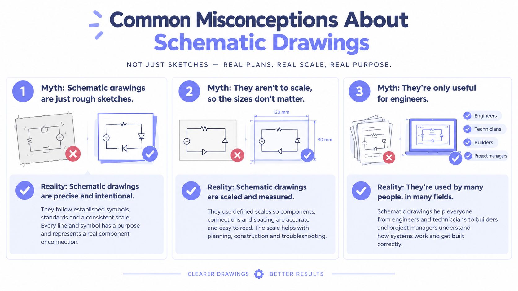
They aren't casual sketches
Schematic drawings aren't napkin doodles. They are scaled, deliberate documents with consistent line weights, room labels, basic clearances, and enough dimensional control to test whether the program works.
A schematic plan may be visually simple, but simplicity comes from editing. If the team can't explain the wall hierarchy, room labels, circulation, and assumptions, the drawing isn't clear enough for review. Treating it as throwaway work weakens client trust because clients use the set to judge whether the architect understands their project.
They aren't suitable for bidding
A contractor can't reliably price or build from a schematic set alone. The drawings generally lack the structural dimensions, material specifications, coordinated consultant information, detailed schedules, and MEP routing required for construction.
A contractor who prices against an incomplete set may add allowances to protect against uncertainty, decline to bid, or return a number that changes substantially as information arrives. That isn't a failure of schematic design. It means the document is being asked to perform a construction-document function.
They don't remove the architect from the process
Automated massing and AI rendering tools can accelerate visualization, option-making, and presentation. They don't decide whether an adjacency is appropriate, whether an egress route works, or whether the program satisfies the client's actual priorities.
The architect still owns the spatial, code, and program decisions. Automated output must be checked against the source plan, especially around openings, stairs, room proportions, and circulation.
The working rule is straightforward: schematic drawings are decision tools, not finished products. Their value is measured by the clarity of the conversation they create, not by how much detail can be fitted onto a sheet.
Frequently Asked Questions
Schematic drawings are scaled, code-aware spatial diagrams between programming and design development. They make decisions visible, test the program, and preserve flexibility before detailed coordination begins. The next handoff is design development, where the selected concept gains coordinated structure, systems, materials, and dimensions.
How long does schematic design typically take?
For a small project, schematic design typically lasts two to four weeks. Complex programs, difficult sites, multiple stakeholders, or extensive jurisdictional review can require longer.
What scale should schematic drawings use?
Common conventions include 1:200 or 1:100 metric, and 1/8 inch or 1/4 inch per foot imperial, selected according to project size and the information that must remain readable.
Can a client build from schematic drawings?
No. Construction documents are required before building because contractors need coordinated dimensions, specifications, schedules, details, and consultant information.
When is AI rendering useful?
AI rendering is useful for early concept reviews and competition entries when the audience needs to understand atmosphere or volume. It isn't a substitute for final approvals, coordinated documentation, or code review.
For a plan-based presentation, Vizcraft's ISO Mapper can turn a clean schematic base into an isometric option quickly. Visit Vizcraft to try it with 2 free credits, no card required, and keep the resulting visuals tied to the decisions in your drawing set.